How Does a Conductivity Sensor Work?
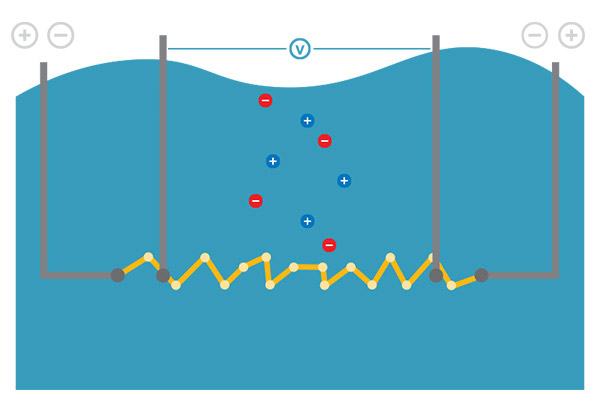
Conductivity sensors are surprisingly straightforward. They all have a conductivity cell or sensing area, which generally consists of electrode pairs to which a current is applied. The voltage is measured, and conductivity is calculated.
Number of Electrodes
A “classical” conductivity cell consists of two electrodes and is best suited for low-conductivity solutions, such as ultra-pure water. The IDS 4320 conductivity sensor for the YSI MultiLab is ideal for measuring in these applications.
It’s important to note that two-electrode cells are susceptible to polarization, and when polarization between the liquid and electrodes occurs, the sensor can show artificially low values.
A four-electrode cell is made up of two voltage electrodes and two current electrodes. This design compensates for coating and buildup, which makes it relatively unaffected by polarization and is thus appropriate for use in most applications. This cell type usually has a wide measurement range, but it may not be as accurate as two-electrode cells in ultra-pure (low conductivity) solutions.
Most YSI conductivity sensors have four electrodes, including the EXO Wiped Conductivity/Temperature Sensor, the EXO Standard (non-wiped) Conductivity/Temperature Sensor, and IQ SensorNet TetraCon Sensors.
A four-electrode cell features two voltage electrodes and two current electrodes. This design helps compensate for scale or buildup on electrodes, making it relatively unaffected by polarization.
In summary, two-electrode cells are better for measuring very low conductivity solutions, while four-electrode cells are best used with high ionic activity.
Cell Constant
Now, let’s move on to the length and area of the conductor. As a reminder, the conductor is the sample liquid, and conductivity is defined as conductance per unit of conductor length. The industry standard unit of conductor length is a 1 cm3 cube of fluid at a specified temperature. Therefore, the ideal conductivity cell is a 1 cm3 cube.
Cell geometry affects your sample’s measured values, and not every sensor is designed to precisely measure a 1 cm3 cube of liquid. This is okay, as we account for this with the cell constant.
Cell geometry defines the cell constant, accounting for the size and shape of the sensor. The cell constant multiplied by the conductivity measurement results in comparable data across sensor variations.
The cell constant is the distance between the electrodes in a sensor divided by the cross-sectional area of the electrodes. This means the “ideal” cell we referred to above (1 cm cube) is 1 cm over 1 cm squared, making the cell constant 1 per centimeter.
While a cell constant is relatively stable, it will drift over time with use, as every time the sensor is submerged, the cell can experience buildup. Even when carefully cleaning the cell with a brush, the surface of the electrodes can be slightly changed. Therefore, the cell constant must be updated to account for these changes—this is done through calibration.
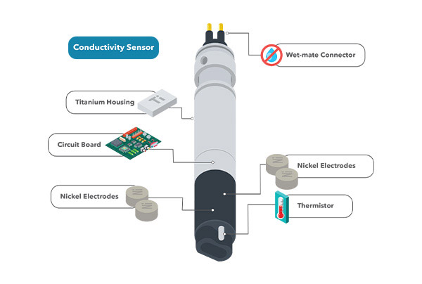
Anatomy of the EXO Standard (non-wiped) Conductivity/Temperature Sensor. It features a wet mate connector, titanium housing, a built-in thermistor, and a 4-nickel electrode cell. It is a smart sensor with an internal circuit board that processes the signal and saves calibration information.
Temperature Coefficient
In addition to the cell constant, the temperature coefficient is another critical factor that impacts the measured value. We know that conductivity is very dependent on temperature. In fact, conductivity can vary up to 3 percent for a single degree of temperature change.
The temperature coefficient is equal to the percent change in conductivity for each degree Celsius change in temperature. Unfortunately, this is not calculated for you, as is the case with your sensor’s cell constant. The temperature coefficient will vary depending on the sample’s composition, but you can find this information from published data or by checking measurements of representative samples.
Let’s consider an example. At 25 °C, our conductivity standard solution reads 1,413 µS/cm. At 26 °C, it reads 1440 µS/cm. We determined the conductive value increased by 1.91 percent per 1-degree change in temperature, making the temperature coefficient 0.0191. This is the default value for YSI EXO and Pro Series temperature coefficients and allows for the calculation of specific conductance.
While much of the heavy lifting in calculations is done for you by our software, it is essential to understand where these values come from and how we compensate for different factors.
Want to learn more about the measurement of conductivity? Check out our webinar on How Conductivity Sensors Work!